Device Overview
The Log4 PoE is a circuit measurement tool that displays accurate readings of voltage, current, and power while also simultaneously logging all measurement data to a MicroSD card and/or the free dedicated PC software Log4.Desktop. The Log4 PoE device is specifically designed to measure the voltages of Power over Ethernet (PoE) connected equipment with high accuracy.
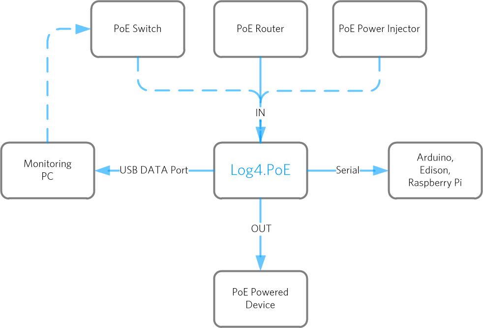
Fig. 55 Log4 PoE System Diagram
At the heart of the Log4 device is a 32bit ARM Cortex M0+ microcontroller which consumes tiny amounts of power while still managing to synchronize numerous simultaneous interactions between peripherals such as the SD card, display, serial data port, and sensing system.
Using a gutsy little processor has enabled the Log4 device to support the writing of standard CSV formatted data to SD card with files sizes only limited by the SD card. If a log of up to 2GB of power, voltage, and current data in a single recording is required, potentially stretching for weeks, then a Log4 device will help to achieve this.
We have worked diligently to create a device which not only connects to a PC but can also be operated as a stand-alone logger with a battery life of up to a week for fast recording rates and continuous measurement display. This is achieved by incorporating a large lithium polymer battery AND one of the latest high speed/low power display technologies called Memory LCD, developed by Sharp Microelectronics.
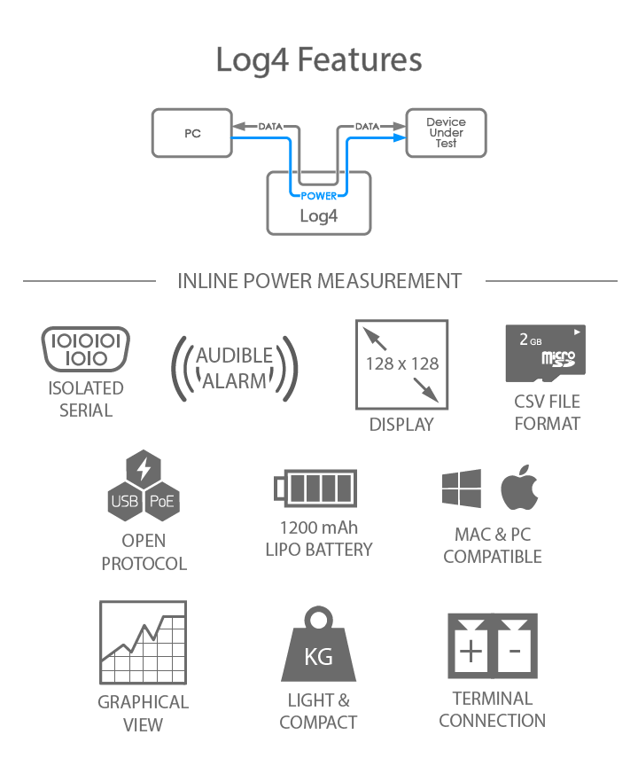
Fig. 56 Log4 Features
What is Power over Ethernet (PoE)?
PoE describes systems that pass electric power along with data on twisted pair Ethernet cabling which supports multiple power levels: IEEE PoE(13W), IEEE PoE+(25.5W), and IEEE PoE++(71W). Our device is equipped with all three power levels.
A complete PoE system includes Power Sourcing Equipment (PSE) and Power Device (PD). PSE is the device that provides power on the Ethernet cable, and manages the whole Power over Ethernet powering process. PD is the device powered by the PSE such as IP phones, IP cameras and wireless access points, etc.
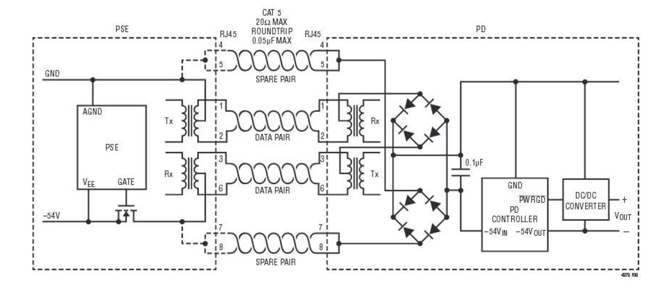
Fig. 57 PoE system basic circuit diagram (courtesy of Linear Technology)
In our Log4.PoE device “DATA PAIR” wires are regarded as Channel A and “SPARE PAIR” as Channel B.
Power transmission modes
There are two modes of power transmission (Fig. 58)
Mode A(End-span units): Using pin pairs 1-2 and 3-6 to transmit and receive both data and power, pinout 4-5, 7-8 left unused.
Mode B(Mid-span units): Using pin pairs 4-5 and 7-8 to transmit both data and power, the remaining pins used for data transmission only.
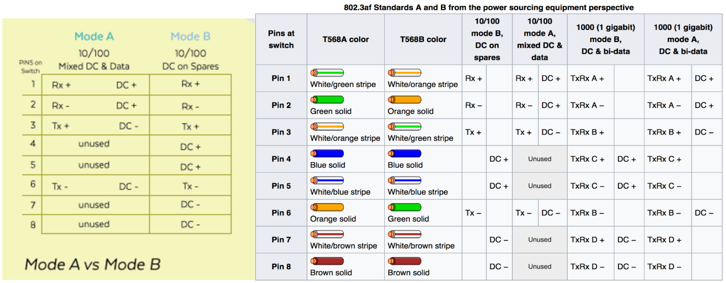
Fig. 58 Power transmission modes
For PoE++ all four twisted wires are used for power transmission. The 802.3bt standard will be able to achieve 49-70 watts of power using this method, by essentially combining both Mode A and Mode B. This newer standard will not only allow for higher power, but will also be able to support 10 Gbps connections.
Log4.PoE device is capable of measuring both Mode A and Mode B voltage, current and power data.
Safety Information
Please follow these guidelines to avoid injury to the device, property, user, or other. Read all safety information before using this product.
Do not exceed the absolute maximum ratings for the sense input terminals or serial monitor I/O.
Voltage Range |
0-70V |
Current Range |
50uA-5000mA(2500mA per channel) |
Do not expose the input sense terminals to reverse voltage conditions.
Do not use the product around explosive gas, vapour or in wet, damp or dusty environments.
Do not touch voltages greater than 30 V AC RMS, 42 V AC peak, or 60 V DC.
Ensure the case does not have any cracks or missing plastic before using the product.
Do not discard the product in domestic/household waste.
Technical Specification
Voltage Range |
0-70V |
Current Range |
50uA-5000mA(2500mA per channel) |
Resolution |
24bit |
Channels |
2 Channel |
Sampling internal Adjustable |
1ms-60min |
Sensing Architecture |
Integrated |
Support Data Pass-through |
Ethernet |
Micro SD card format |
FAT-32 |