User Interface
Front Panel Controls
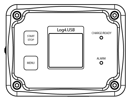
Fig. 11 Front panel of Log4.USB
START/STOP button: Short press once to start up Log4.USB, press and hold to turn off Log4.USB. When Log4 device is on with a micro SD card inserted, short press to start/stop logging data onto SD card.
Menu button: Access Settings and Toggle back and forth between screens.
Alarm lights will light up when voltage and/or current limit has been exceeded.
Charge/ready turns red during charging if device battery is not full, turns green when fully charged.
Bottom and Side Panel Controls
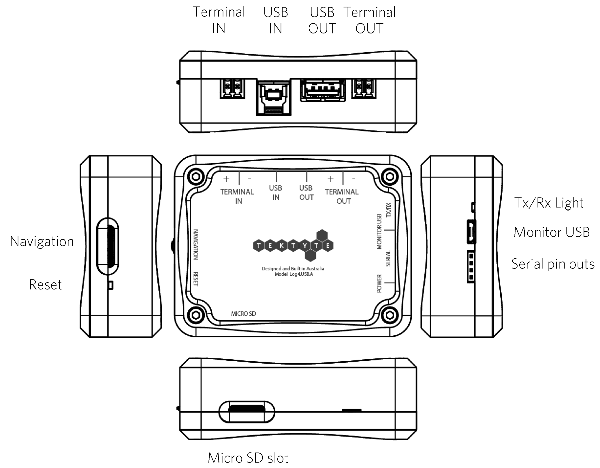
Fig. 12 Bottom and side panel of Log4.USB
Terminal IN (+/-): Pin connection to the Power Supply.
USB IN: Connects to the USB power supply (ie. PC/ USB Hub).
USB OUT: Connects to the device that the user would like to measure (ie. Raspberry Pi, Arduino).
Terminal OUT (+/-): Pin connection to the Power Supply.
Tx/Rx Light: light up during serial communication.
Monitor USB: Log4 Charging port and communication to PC.
Serial Pin outs: Serial connection to external devices .
Micro SD: Mirco SD card slot.
Reset Button: Short press the button located inside the small hole on the left face of the Log4 device using a thin object, such as a push pin, to reset the device to stored settings from the last power-off. The date and time will need to be set again.
Navigation button: This is in the form of a scroll wheel on the left side of the device Scroll up and down to slide between options, press inwards to select option.
Monitor USB and Serial
Tx/Rx: Transmitter and receiver indication light.
Monitor USB: Charge Log4 device and exchange serial data between PC and Log4.
Serial pins: used for serial communication with external monitoring devices.
Power indicates the power PIN position.
Status and Information Bars
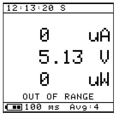
Fig. 13 Default Screen of Log4.USB
On the default screen (Fig. 13):
Top left shows the time.
Beside the time there might be an “S” or “U” or “L” indicating the SD card status (when SD card is inserted). See 5 for more details.
Middle of the screen shows measured current, voltage, power.
Bottom left shows the battery status and sampling period.
Bottom right shows the amount of measurements taking into calculating the average.
There might also be a line “OUT OF RANGE” under the three measurements if measurements are out of range.
Scroll navigation wheel up or down to see screen focusing on current, voltage or power measurements only.
Instead of showing all three measurements at the same time, the screen now shows only the voltage, current or power measurements and their Maximum and Minimum measurements respectively (Fig. 14).
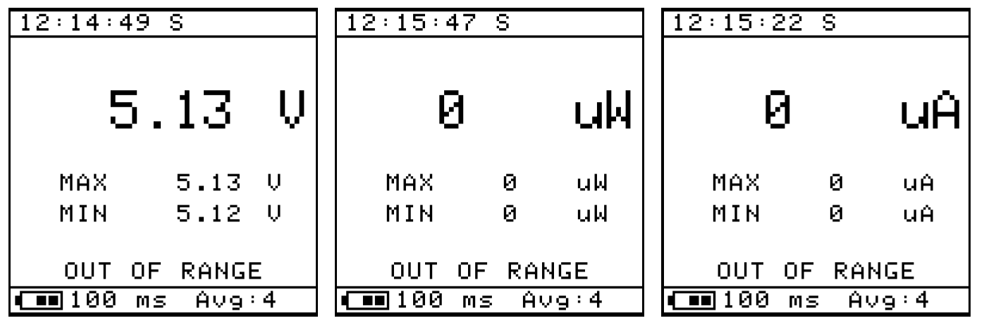
Fig. 14 Individual Measurements
Settings Menu
Sample Period
This Log4 Device has an adjustable Sample Period between 1ms-60min (Fig. 15). Sample Period means how often the measurements are being taken. For example, 1s Sample Period means one sample taken every second.
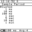
Fig. 15 Sample Period Window
How to set Sample Period on LOG4.USB
Press Menu button to enter Settings Screen.
Press Navigation Wheel to enter Sample Period options.
Scroll Navigation Wheel to choose Sample Period of interest.
Press Navigation Wheel to select Sample Period, “Set!” will appear on screen to indicate the sample period is set.
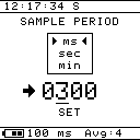
Fig. 16 Current Sample Period Window
For custom Sample Period:
Under Sample Period options, press Navigation Wheel to select Custom.
Scroll up and down to choose the desired sample period unit: ms, sec or min (Fig. 16).
Press Navigation wheel to move to number selection, scroll up or down to change the number, then press navigation wheel to confirm each digit till the arrow pointing at SET, scroll up to finalise the custom Sample Period.
If the Sample Period has been correctly set, it will be displayed at the bottom left of the screen (Fig. 17).
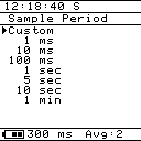
Fig. 17 Updated Sample Period
Press Menu key two times to go back to home screen.
Display Averaging
To filter out short term fluctuations, a moving average filter is used to take the average value from M (measurements) and produce a single output. Higher M is generally used for faster sampling rates. For a given sampling period, higher M also produces more stable values on the Log4.USB screen.
Press Menu button to get to Setting Screen.
Scroll Navigation Wheel down to Display Averaging.
Press Navigation Wheel to enter Display Averaging options (Fig. 18).
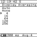
Fig. 18 Display Averaging Screen
Scroll Navigation Wheel to choose option of interest.
Press Navigation Wheel to select option of interest.
If the Display Averaging has been correctly set, it will be displayed at the bottom right of the screen.
Press Menu key two times to go back to home screen.
SD Card
The Log4 device allows the logging of measurements onto a micro SD card. New .csv files are created at the beginning of every session.
Press Menu button to enter Settings Screen.
Scroll Navigation Wheel down to SD Card.
Press Navigation Wheel to enter SD Card.
Enable/Disable Logging by pressing Navigation Wheel. This will only allow the Log4 device to start logging information onto SD card if there is a SD card in place. (A short cut to this is simply pressing Start/Stop button on main screen once the SD card has been inserted)
Display (Invert Display and Back Light)
This part of the settings allows for Invert Display and turning on Back Light.
Press Menu button to enter Setting Screen.
Scroll Navigation Wheel down to Display.
Press Navigation Wheel to enter Display (Fig. 19).
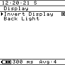
Fig. 19 Display Options Screen
To activate Invert Display:
Press Navigation Wheel to activate inverted display.
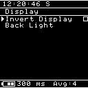
Fig. 20 Inverted Display
To activate Back Light:
Scroll Navigation Wheel down to Back Light.
Press Navigation Wheel enter Back Light Options
Press Navigation Wheel on Enable to activate Back Light
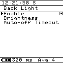
Fig. 21 Activate Backlight
Scroll down Navigation Wheel to Brightness
Press Navigation Wheel on Brightness then scroll up and down to adjust brightness
Press Menu to toggle back to previous screen
Scroll down navigation wheel to Auto-off Timeout
Press navigation wheel to enter Auto-off Timeout options
Scroll navigation wheel up or down to change the time in seconds.
Press navigation wheel to set the Auto-off Timeout options
Alarm (Setting Alarms)
Two types of alarms are available on the Log4.USB - a visual indicator light and an alarm sound (Fig. 22). Both can be triggered by measurements current or voltage measurements above or below the set threshold.
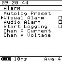
Fig. 22 Alarm Options Screen
Visual Alarm
Red alarm light indicates there are measurements above the high threshold.
Blue alarm light indicates there are measurements below the low threshold.
Purple alarm light indicates some of the measurements are above the high threshold and some of the measurements are below the low threshold.
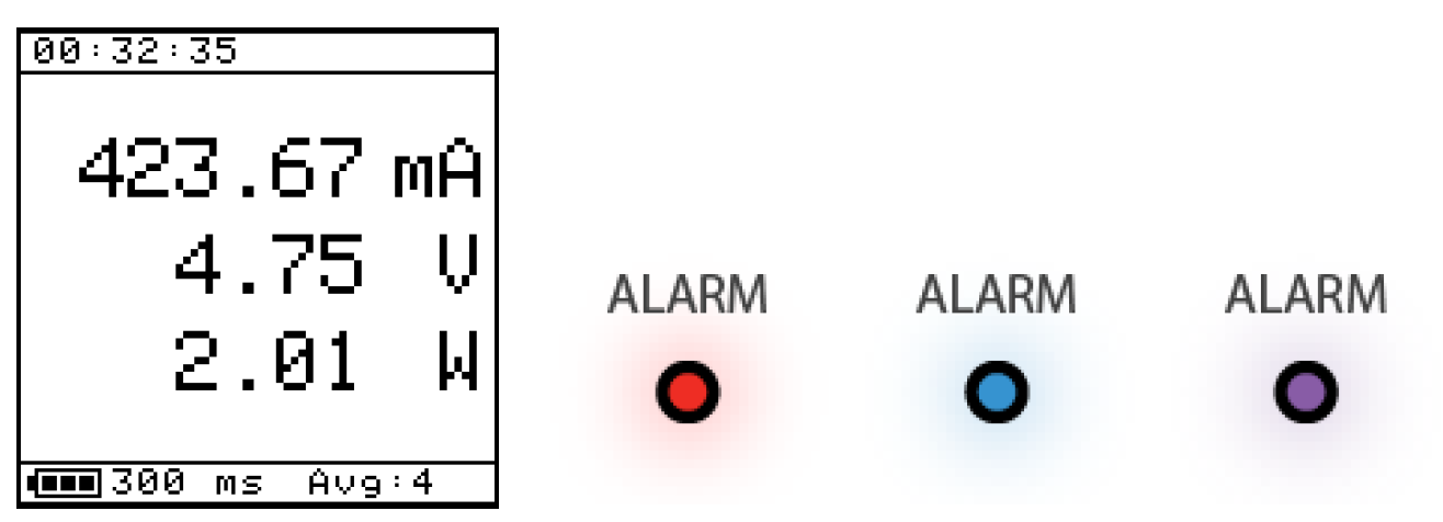
Fig. 23 Log4.USB with red, blue and purple alarm light
To set the High Current Threshold
Using the above example (in Fig. 23), the Red Alarm light can be triggered if the High Current Threshold is set as 100mA.
Press Menu for Settings page.
Scroll Navigation Wheel to Alarm.
Press Navigation Wheel inwards to select Alarm.
Press Navigation Wheel to enable Visual Alarm.
Scroll Navigation Wheel down to Chan A Current.
Press Navigation Wheel to select Chan A Current.
Scroll Navigation Wheel to High alarm En.
Press Navigation Wheel to enable High alarm En.
Scroll Navigation Wheel to High Threshold.
Press Navigation Wheel to select High Threshold.
Now the Alarm value setting page should be visible.
Press Navigation Wheel to move from digit to digit.
Scroll Navigation Wheel on the digit of interest, (in this case 100mA), Scroll the wheel until the number 1 is on the screen (Fig. 24).
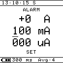
Fig. 24 Current Threshold Screen
Once the value has been chosen, repeatedly press the Navigation Wheel until SET is underlined.
To finalise the selection, scroll Navigation wheel up or down once on SET.
The Red Alarm Light will activate if the visual alarm is enabled and the alarm conditions are triggered.
To set the Low Voltage Threshold
Using the above example (in Fig. 23), the Blue Alarm light can be triggered if the Low Voltage threshold is set as 6V.
Press Menu for Settings page.
Scroll Navigation Wheel to Alarm.
Press Navigation Wheel inwards to select Alarm.
Press Navigation Wheel to enable Visual Alarm.
Scroll Navigation Wheel down to Chan A Voltage.
Press Navigation Wheel to select Chan A Voltage.
Scroll Navigation Wheel to Low alarm En.
Press Navigation Wheel to enable Low alarm En.
Scroll Navigation Wheel to Low Threshold.
Press Navigation Wheel to select Low Threshold.
Now the Alarm value setting page should be visible.
Press Navigation Wheel to move from digit to digit.
Scroll Navigation Wheel on the digit of interest (in this case 6V), scroll the wheel until the number 6 is on the screen (Fig. 25).
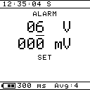
Fig. 25 Voltage threshold screen
Once the value has been chosen, repeatedly press the Navigation Wheel until SET is underlined.
To finalise the selection, scroll Navigation wheel up or down once on SET.
The Blue Alarm Light will be activated if the visual alarm is enabled and the alarm conditions are triggered.
Similar steps can be taken to set Low Current and High Voltage currents, respectively.
Audio Alarm
Using the above example (in Fig. 23), the audio alarm can be triggered if the High Current Threshold is set as 100mA. Buzzing sound will be same for all types of alarms.
To set the High Current Threshold
Press Menu for Settings page.
Scroll Navigation Wheel to Alarm.
Press Navigation Wheel inwards to select Alarm.
Press Navigation Wheel to enable Audio Alarm.
Scroll Navigation Wheel down to Chan A Current.
Press Navigation Wheel to select Chan A Current.
Scroll Navigation Wheel to High alarm En.
Press Navigation Wheel to enable High alarm En.
Scroll Navigation Wheel to High Threshold.
Press Navigation Wheel to select High Threshold.
Now the Alarm value setting page should be visible.
Press Navigation Wheel to move from digit to digit.
Scroll Navigation Wheel on the digit of interest (in this case 100mA), scroll the wheel until the number 1 is on the screen, as in (Fig. 24).
Once the value has been chosen, repeatedly press the Navigation Wheel until SET is underlined.
To finalise the selection, scroll Navigation wheel up or down once on SET.
A buzzing sound will be heard if the audio alarm is enabled and the alarm conditions are triggered.
Log on Alarm
The Log4.USB is able to begin logging to SD once an alarm has been triggered. To enable this feature,
set the alarm thresholds as desired following the instructions of sec_USB_visual_alarm
and sec_USB_audio_alarm. Next, select the Start Logging option on the main alarm screen.
If any of the alarms are triggered, the Log4.USB will start logging measurements to the SD card
at the set sampling rate until the START/STOP button is pressed. Once this automatic logging has been
stopped, the option will need to be re-enabled in the alarm screen.
Autolog Preset
The Autolog Preset function will automatically set some preset alarm settings. These are:
Current high alarm: 500uA
Current low alarm: off
Both voltage alarms off
Visual alarm: On
Start Logging: On
Audio Alarm: Off
To use these presets, scroll navigation wheel to Autolog Preset, and press the navigation wheel. The notice shown in Fig. 26 will be displayed.
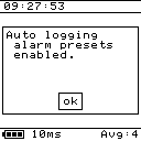
Fig. 26 Autolog preset enabled screen
Zero Calibration
Turn ON Zero Cal to Zero measured currents and voltages (Fig. 27).
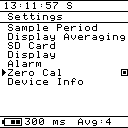
Fig. 27 Enabling Zero Cal option
How to set Zero Calibration
Press menu button for Setting page.
Scroll Navigation Wheel to Zero Cal.
Press Navigation Wheel to turn on the Zero Cal, “Offset Applied” message will show on screen (Fig. 28).
Press the Navigation Wheel again to confirm setting the offsets.
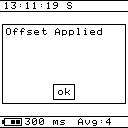
Fig. 28 Offset applied screen
How to turn OFF Zero Calibration
Scroll Navigation Wheel to Zero Cal.
Press the Navigation Wheel to turn off Zero Cal, “Offset Removed” message will show on screen (Fig. 29).
Press the Navigation Wheel again to confirm removing the offsets.
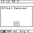
Fig. 29 Offset removed screen
Device Info
This page is a summary of the Log4 device information.
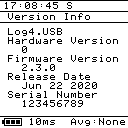
Fig. 30 Log4.USB Device info screen
For optimum performance make sure the device has the latest Firmware Version.
Set Date/Time
Log4 Devices automatically syncs date and time when they connect to the Log4 Desktop Software, however user can still manually set date and time.
Press menu button for Settings page.
Scroll Navigation Wheel to Date/Time (Fig. 31) and press it to navigate to the sub menu (Fig. 32).
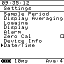
Fig. 31 Log4.USB Device Settings Screen
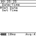
Fig. 32 Log4.USB Device Sub Menu Settings Screen
How to set Date
While in the Date/Time Setting (Fig. 32) sub menu, navigate to “Set Date” and press the navigation dial to enter Set Date screen (Fig. 33).
Press the Navigation Wheel to move to different parts of the date and scroll to change the corresponding value.
After entering the correct date, press the Navigation Wheel again to move over to “SET” option and then either scroll Navigation Wheel UP or DOWN to save the current date.
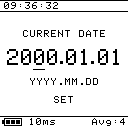
Fig. 33 Log4.USB Device Set Date Screen
How to set Time
While in the Date/Time Setting (Fig. 32) sub menu, navigate to “Set Time” and press the navigation dial to enter Set Time screen (Fig. 34).
Press the Navigation Wheel to move to different parts of the time and scroll to change the corresponding value.
After entering the correct time, press the Navigation Wheel again to move over to “SET” option and then either scroll Navigation Wheel UP or DOWN to save the current time.
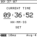
Fig. 34 Log4.USB Device Set Time Screen